

Product drawings are the technical language for communication between designers and related personnel. They are the standards and guidelines for processing, inspection, assembly, and maintenance.
Understanding product drawings is a basic requirement for relevant practitioners. A qualified drawing must first comply with mechanical industry standards, which helps facilitate communication among relevant personnel and improve efficiency.
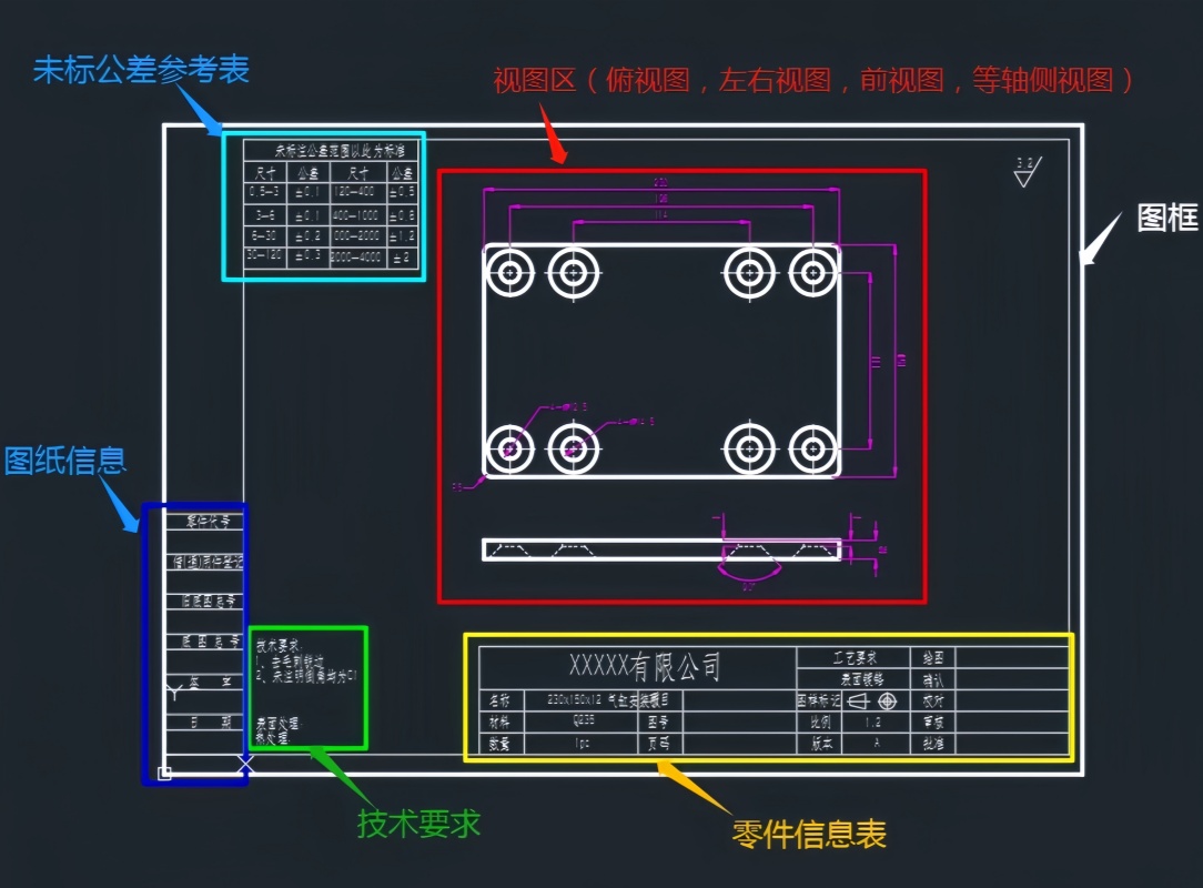
To understand a product drawing, the following points should be focused on:
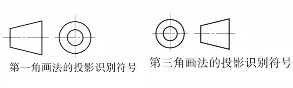
First: Projection views of the drawing: When viewing the drawing, first observe the projection symbols on the drawing to determine the projection angle and avoid reading the wrong drawing.
The projection angle is a concept derived when a three-dimensional model is converted into a two-dimensional drawing. There are two projection methods: the first angle and the third angle. The first angle can be understood as light shining on the surface of an object and projecting the illuminated image behind the object (commonly used in countries such as China, Germany, and Russia). The third angle can be understood as "topping", where a plane is placed on the surface of the object and the image is depicted in front of the object through perspective (commonly used in countries such as the United States, the United Kingdom, and Japan).
First, identify the main view, and then analyze the names of other views based on the corresponding relationship, section position symbols, and the projection direction of the view.
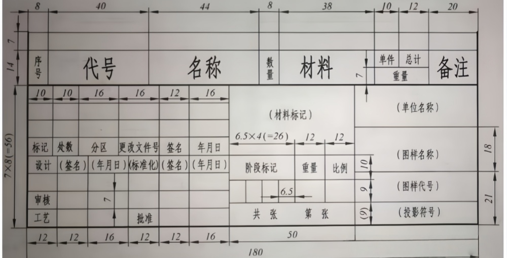
Second: Title block and detail list
The title block is usually located in the lower right corner of the drawing, with its long side parallel to the long side of the drawing. For A4-sized drawings placed vertically, the title block is located directly below the drawing. From the title block, you can learn the name, material, scale, and purpose of the part.
Third: Technical requirements
Technical requirements are clearly stated using specified symbols, codes, marks, and text to provide the technical indicators and requirements that the part should meet during manufacturing and inspection, such as dimensional tolerances, surface roughness, heat treatment, and testing methods.
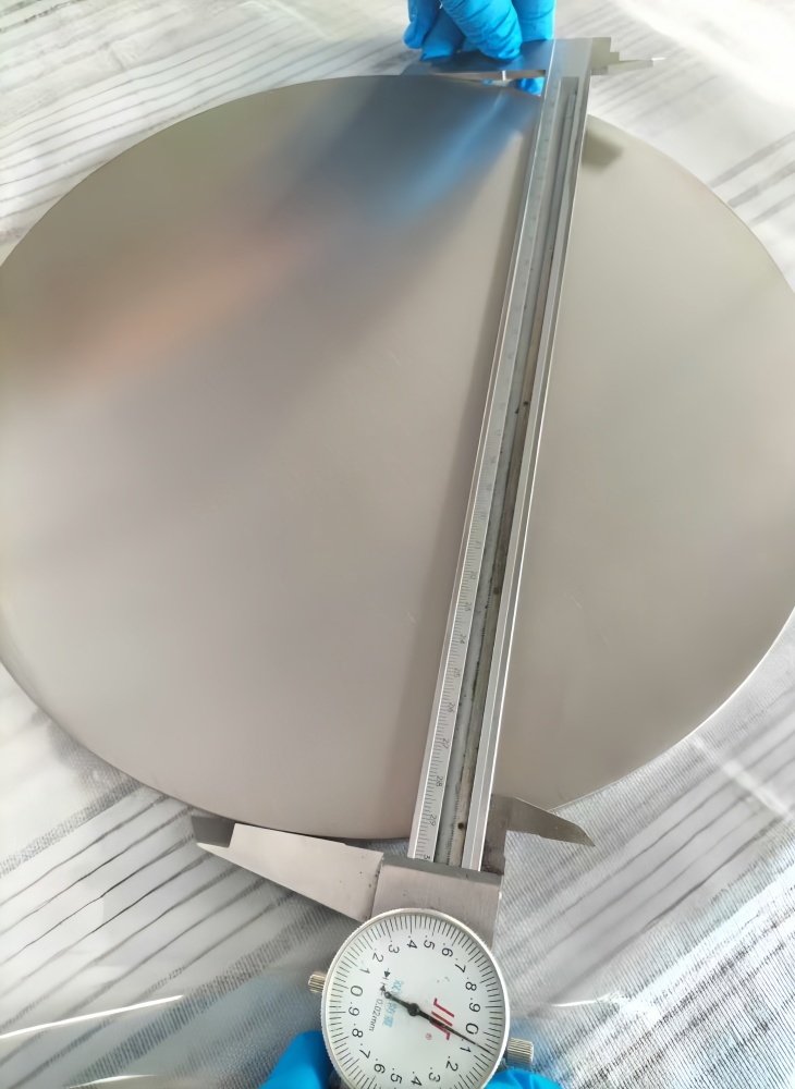
Fourth: Dimensional marking on the part drawing
a. Dimensional reference selection
The dimensional reference is the starting point for measuring dimensions. Each part has three dimensional references in the length, width, and height directions. For more complex parts, in addition to the main reference in each direction, there are often auxiliary references.
b. Dimensional marking
When marking dimensions, start from the reference and mark the positioning dimensions and shape dimensions of each part.
c. Precision requirements in the part drawing.
Fourth: Construct the 3D solid structure of the part.
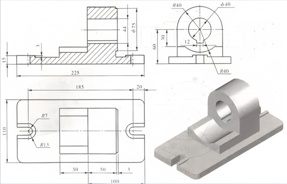
From 2D to 3D, refer to the provided solid graphics (not all drawings have solid diagrams), and gradually imagine the structure and shape of the part.

In conclusion, product drawings are the language for communication between designers and related personnel. Reading and understanding drawings is not an innate skill. Any practitioner can become a qualified professional by strengthening skill training, mastering scientific methods, and engaging in deliberate practice.
 +86-0917-3217876
 18292732691
 No. 28, Middle section, Baoti Road, Weibin District, Baoji, Shaanxi
 marketing@ymdtitanium.com
 www.ymdtitanium.com


 English
 简体中文
简体中文
 18292732691
 marketing@ymdtitanium.com
 zyh2968808781
 +86 18292732691
 .cid.b0f8e930cd0ba28e
